Raspberry Pi 120V AC Switch
Pre-built commercial AC Power Relays
Commercial units Notes:
| Price | Description/Link | Notes |
|---|---|---|
| $15 | IoT Power Relay (Spec) (OEM) | 2-wire control Amazon spotty availability, now $27. Sparkfun price also $27 |
| $16 | 4 SPDT Power Relay, DC5V | No 120V Receptacle |
| $40 8 channel I2C Solid State Relay $10 I2C Cable Kit 4 pin | (not purchased) | |
| $13 | Enclosed AC/DC Power Relay | No 120V Receptacle Uses 120V AC to control a relay. Not suitable for 5V control of 120V AC |
- The IoT Relay is awesome at $15. At closer to $30, it is still a really good deal. Self-contained, multiple receptacles, normally open and normally closed, and 2-wire control. If you want to control 120V AC with your Raspberry Pi, start here (if you can find it in stock).
- The Enclosed AC/DC Power Relay was included only for completeness. It is not suitable for a Raspberry Pi project (unless you want to build a “line-voltage detector” – i.e. detect when the power goes out)
Component List for home-made Power Relay:
| Price | Description/Link | Notes |
|---|---|---|
| $10 | Project Box, 4.5×3.5×2.2 | 3.2mm thick |
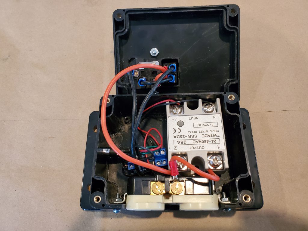
| $15 | 2x Solid State Relay, 25A, 3-32V DC | Has “on” LED |
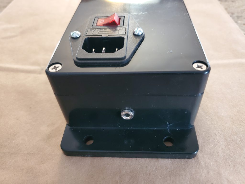
| $8 | 3x Power Inlet, Fuse, Switch | Switch has light |
| $12 | 10x Power 5-36V MOSFET, with control board | Board SMD LED |
| $8 | 50x Blue PCB Mount Screw Terminal | optional |
| $8 | 10x 3 Pin Power Socket Plug Panel | Not used, not screw mounted |
| $14 | Wire, Silicone 16 Gauge, 25ft Black and Red | Careful with the link – when out-of-stock, switches to 10 Gauge |
| $8 | 5x 1/8″ 3.5mm TRS Stereo Panel Mount | |
| $9 | 10x 1/8″ 3.5mm TRS Male Plug 3 pole | |
| $9 | 3x 1/8″ 3.5mm TRS 3 pole to screw terminal | Testing only |
| $18 | 10x Duplex Receptacle Outlet, 3-wire, 15A, 10x Tamper-Resistant Decorator Receptacles | Not purchased. Decorator style. |
| $16 | 480pcs Insulated Wire Connectors $20 1200pcs Electrical Connectors, with spades $18 Wire Crimper Tool | Optional |
Build Notes:
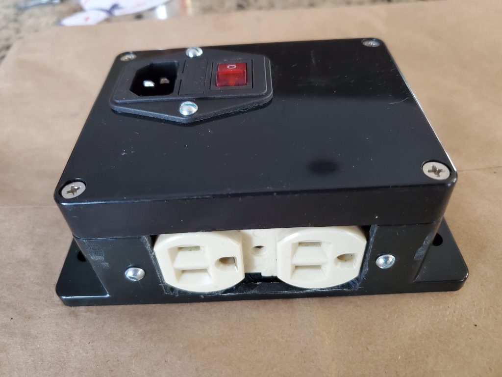
- The receptacle used was a “left over” from a previous project. This is only important because the project box used is barely able to fit this (unknown model/brand) receptacle. If your receptacle is physically longer/taller (by even 1/16″), it either will not fit or will warp the project box so that the lid no longer fits. A “decorator” style receptacle would get rid of the ugly “dent” in the middle, between the sockets.
- Ended up with a 3-wire control. The connector used was a stereo L/R/ground 1/8″ jack and plug. Very rugged, but also very “non standard”. At least nothing will catch fire if you plug headphones into the jack.
- The SSR is total overkill at 25A, especially since the intake fuse is 5A. But, in theory, the fuse can be swapped with something up to 10A.
- The 3 Pin Power Socket Plug was not used because it uses friction to hold it in place. Maybe J-B Weld or Gorilla Glue Epoxy could have been used. Instead, used a 2-socket receptacle mounted on the side of the project box.
- The 1200pcs is only $4 more, and comes with “spade” connectors, and would have been more useful for this build.
Total Cost Notes:
$25 = Cost of the hand-built, per unit: $10 + $8 + $3 + $1 + $1 + $1 + $1 = $25, plus tools (Dremel with cutting wheel)
Other Notes:
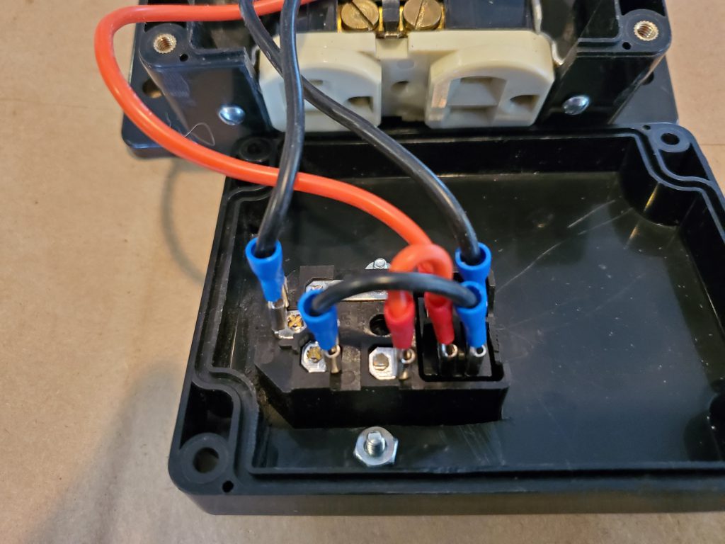
- For sure the best discovery during this project was the “MOSFET on a board“. At $1 each, it is basically the same price as the MOSFET itself, but also contains resistors, indicator LED, and binding posts. It is used here as a simple on-off to control the SSR, but is also capable of PWM to a motor. Note: Even though there are two FETs on the board, the “400W” claim seems outrageously high (and possibly dangerous).
Project Photos: